| |
| |
CVT ( CONSTANT VOLTAGE TRANSFORMER ) |
|
|
| |
|
|
| |
 |
|
| |
|
|
| |
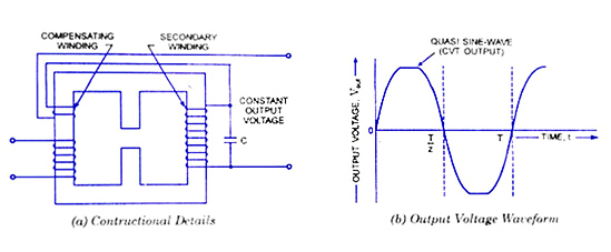
With the popularisation of PCs & Electronic Equipment, the constant voltage transformers (CVTs) have also become equally popular. The CVT is simply a magnetic transformer of a special construction that has a capacitor connected across the secondary winding of the transformer. In an ordinary transformer, the primary and secondary windings are wound near each other so that whenever there is a change of voltage across the primary there is a corresponding change in the secondary voltage depending upon the ratio of the turns on the two windings. However, in a CVT the primary and secondary windings are wound
|
|
|
|
| |
| |
|
|
separately from each other, as illustrated in figure. To set up field in between the coils, a separate shunt path is provided between the two windings but an airgap is formed in the shunt path. A capacitor is connected across suitable tappings of the secondary winding. The constructional details of a CVT are shown in the figure.
The reason we use a CVT and not a voltage stabilizer for computer applications is that in the voltage stabilizer relays are present and when these relays operate (switch), the output voltage may be interrupted for a short time. Such a
|
|
|
| |
|
|
|
transient may not be desirable for computers which may cause the computer to reboot. Also, the CVT provides a clean spike-free output voltage. The voltage regulation possible in a CVT also is good.
|
|
| |
|
|
| |
SALIENT FEATURES |
|
| |
- Stabilizer, Spike Suppressor, Line Filter, Isolation Transformer ALL IN ONE
- Built-in Short Circuit & Overload Protection
- No interruption at output for small duration line interruptions/Brown-outs.
- Built-in Spike, Surge & RFI Suppression
- No electrical noise, as no moving parts or semi-conductors are used.
- 100 times faster than servo stabilizer.
- Can work at very low voltages on partial load & Instantaneous voltage regulation
|
|
| |
|
|
| |
Technical Specs :
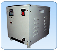
"PERFECT CVT" are available in a wide Range from 50 VA to 5000 VA with load test conducted at unity power factor for all ratings. |
|
| |
|
|
| |
|
|
| |
|
|
| |
|
|